Industrial Wastewater Treatment
Industrial Wastewater Treatment
VisitCount 134
Types of Industrial Wastewater Treatment
Because industrial wastewaters vary greatly in the types of pollutants they contain and because of the harmful impact these industrial effluents have on the environment, different methods have been designed and are used to treat industrial wastewater. Below we describe the different types of industrial wastewater treatment methods, including the method used at Denafonoon (a company active in industrial wastewater treatment). It is worth noting that selecting the best method for treating industrial wastewater depends on several factors. The most important factors for choosing a treatment method are as follows:
- The type and concentration of pollutants (fats/oils, heavy metals, suspended and colloidal solids)
- Quality indices such as BOD, COD, TSS and pH
- Influent flow (wastewater volume)
- Required effluent quality (for discharge to the environment or for reuse)
Based on these parameters, a decision can be made to use physical, chemical, or biological treatment methods. The common methods of industrial wastewater treatment are described below.
1. Physical treatment
In this stage, large solid particles and coarse suspended materials are separated from the wastewater stream. Tools such as manual and mechanical bar screens, various meshes, and classifiers (for sand/grit removal) can remove up to about 95% of sand and grit. This step is essential to reduce the initial load on the system and to prevent damage to downstream equipment.
2. Chemical treatment
In this method, chemical additives are injected to cause coagulation and flocculation of colloidal particles and other pollutants so they can settle. Equipment such as API separators, DAF (Dissolved Air Flotation) units and CPI and various clarifiers and oil skimmers are used to remove oils and greases. Also, pH adjustment and the use of flocculants (cationic or anionic) play an important role in improving effluent quality.
3. Biological treatment
This section is used to remove organic matter and harmful microorganisms, and it includes two main groups:
- Aerobic processes: such as activated sludge, CPF systems, SBR, and MBR, which use aeration and aerobic bacteria to break down pollutants.
- Anaerobic processes: such as the UASB system, which degrades organic pollutants and produces biogas.
Important notes when choosing the correct treatment method
- In all methods, the sludge and sediment produced must be managed and collected using equipment such as sludge-scraper bridges (clarifier bridges) or sedimentation systems.
- Selecting the appropriate method requires a detailed examination of the wastewater characteristics and the operating conditions.
- Today, industrial treatment packages (systems) combine physical, chemical and biological methods with custom design to meet the needs of various industries.
Industrial Wastewater Treatment Package
Industrial wastewater treatment can be carried out by various methods; one common approach is to use an industrial wastewater treatment package, which comprises a set of equipment for the wastewater treatment process and generally includes both physical and chemical treatment stages.
One of the problems many industrial owners face today is the industrial wastewater produced in their factories. Industrial effluents are not only hazardous to the environment, but if they are not properly treated and reused in production lines, they also cause problems for the industry—such as high energy consumption and excessive wear-and-tear on equipment.
Denafonoon is one of the manufacturers of industrial wastewater treatment systems in Iran. To address problems related to industrial wastewater treatment, the company has designed and manufactured a system with high efficiency that treats wastewater and returns treated water to the production line.
The designed system for treating industrial wastewater is commonly called a wastewater treatment package and filter press (the “wastewater treatment and filter-press package”). This system is one widely used industrial water treatment solution and finds application across many industries. It can be used to treat industrial wastewaters from:
- Sand and gravel plants
- Copper mines
- Acidic industrial effluents
- Sanitary/municipal-type wastewater streams produced in industries
- Petrochemical plants
- Pharmaceutical industry
- Dyeing and textile industries
- Electroplating
- Oil industry
- Tile and ceramic industry
- Power plants
- Stone quarries
- Agricultural and livestock industries
- Car wash facilities
- Cardboard/packaging industries
- Brick manufacturing
- and others
In fact, the treatment process in the wastewater treatment + filter-press package is performed in a similar sequence for different industrial effluents. What differs between wastewater streams from various industries is the *nature* (composition) of the water; that is why there are specific requirements—such as the choice of filter-press plate material or the selection of a filter cloth compatible with the wastewater—to be considered in the treatment design. You will become familiar with many of these aspects through the rest of this article.
Summary of how the wastewater treatment + filter-press package works
- First, the raw solution containing coarse solid particles (referred to here as wastewater or effluent) passes through a screen (bar screen) located at the inlet, which prevents large solids from entering and damaging pumps, piping, valves, etc.
- Next, the influent is stored temporarily in a basin called the “dirty-water tank.”
- From there, the wastewater is pumped as required into a settling basin called the clarifier tank—one of the components of the treatment package.
- Simultaneously, during transfer, a polymeric settling aid solution (a flocculant solution) prepared by the flocculant preparation and dosing unit is dosed into the stream to accelerate particle settling.
- The settled sludge is transferred by an automatic control valve into the sludge homogenizer tank (sludge mixing/homogenization tank).
- After homogenization with a mixer, the suspension is delivered and pumped (by a single- or two-speed pump) into the filter press.
- Inside the filter press, under the pressure generated by the feed pump, the liquid passes through the filter cloth/membrane while solids remain on the cloth and form a filter cake.
- After a suitable dewatering period, the cake thickness fills the gap between two plates; then, by opening the press plates (manually or automatically), the cake is discharged from the machine.
- The clean water (final product) is collected in Tank No. 10 and can be returned to the factory production line.
This article aims to provide a complete explanation of the operation of the filter press and the wastewater treatment package (one type of industrial wastewater treatment composed of several treatment units). A photo of the setup is embedded on the original page. This information will be very helpful when buying a filter press and a wastewater treatment package—so please read on.
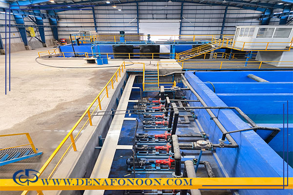
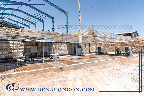
Layout of the wastewater treatment package (as shown in the picture)
The package is arranged such that the basin and the filter-press units are on the sides and the tanks are in the middle. Below we list these components and describe each one’s function:
- Dirty-water tank (inlet basin)
- Filter-press valve and associated valves for the package
- Flocculant preparation and dosing unit
- Industrial water treatment tank (clarifier tank)
- Clean water tank
- Filter press
- Homogenizer tank (sludge homogenizer)
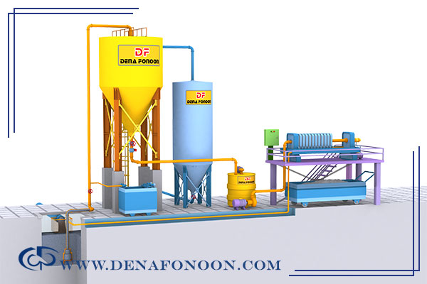
In the picture below the various parts of the wastewater treatment package and filter press are labeled for your familiarity. Note that this illustration is for familiarization; actual equipment layout may differ in practice. Nevertheless, the descriptions below apply to all layout variants in the same order.
How the wastewater treatment package and filter press operate
We can call the wastewater treatment package + filter press a packaged industrial wastewater treatment system. To better understand the package operation, refer to the layout: the basin and the filter press are at the sides and tanks are in the middle. Below, each component is named and its function explained.
1. Dirty-water tank (inlet basin)
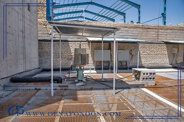
The dirty-water tank is one of the essential components in industrial water treatment and includes the following items:
- Bar screen (inlet screen)
- Pump
Each is described below.
Bar screen (inlet screen):
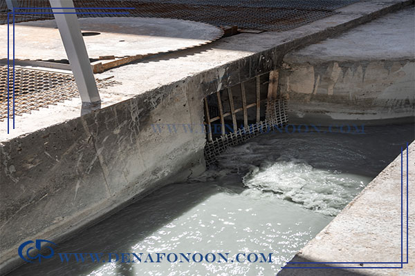
In the figure this screen is labeled as the strainer. The reason for installing this screen at the wastewater inlet is to prevent foreign objects—such as stones (which increase pump and piping wear over time), glove pieces, wood fragments, etc.—from entering subsequent tanks or treatment units. If such solids enter downstream components, problems may occur, including:
1. Blockage of inlet and outlet passages
2. Motor jamming
3. Increased pump wear
The presence of this screen at the inlet to the basin prevents these solids from entering the basin and effectively eliminates potential treatment problems.
Pump:
The pump installed in the dirty-water basin can be designed and configured in several ways; types mentioned here are all centrifugal pumps (i.e., any pump that operates by centrifugal force and has an impeller is a centrifugal pump). Common types include:
1.Vertical (vertical turbine) pump: This model is designed such that the motor sits above while the impeller and pumping section are placed at the bottom inside the basin. This vertical type is one of the most commonly used pumps in dirty-water basins.
2. Submersible pump: In this pump the entire motor is submerged under water; submersible pumps are commonly used in pools, wells, etc. The function of the pumps placed in the basin is to lift wastewater from the bottom of the basin into the discharge piping.
2. Filter-press valve and package valve
The flow rate into the industrial water treatment tank (clarifier) can be regulated by this valve. The valve has a blade (or tongue) that causes turbulence in the flow. From a fluid-mechanics viewpoint, when the flow strikes this blade, it creates turbulence in the fluid and the turbulent region propagates downstream; in practical terms this adjusts the load (current draw) on the clarifier feed pump motor.
3. Flocculant preparation and dosing unit
This unit is responsible for mixing water and flocculant powder and dosing this solution into the industrial water treatment line. (To learn about flocculant powder commonly used in wastewater treatment, the original text referenced a link.)
Preparing the flocculant solution
There are two methods to prepare the flocculant solution:
- Manual method
- Automatic method
1.Manual method
In the manual method the preparation of the flocculant solution is done manually and imprecisely: all quantities of water and flocculant powder are mixed empirically without precise measurement, which causes many problems.
Disadvantages of manual flocculant preparation:
- The amount of flocculant powder added is adjusted by eye and may be under- or overdosed.
- The amount of water used for dissolution is estimated visually and can have large errors.
- Mixing (dissolution) is done manually and at poor quality.
- All materials are mixed in a single tank, and multi-chamber tanks are not used.
Another problem with manual dissolution is that some flocculant polymer molecules may not dissolve properly due to reasons such as:
- Too much flocculant powder being added.
- Insufficient dissolution water.
- Inadequate space/volume for the powder to dissolve.
- Insufficient mixing time.
- Lack of proper monitoring and control of powder dosing.
Automatic method
For a uniform and more accurate flocculant solution, a flocculant preparation and dosing unit is recommended. This unit is used in both modern and traditional treatment packages.
It is important that in traditional treatment setups this flocculant preparation/dosing unit be used without its own pump in some cases, because in such systems there is no dedicated pump and piping that would pump the solution into the clarifier tank and mix with sludge. In a modern wastewater treatment package with a clarifier tank, the flocculant solution should be pumped into the pipe leading to the clarifier.
Using a dedicated flocculant preparation/injection unit ensures thorough mixing of the powder and water and yields a clear, homogeneous solution.
In traditional systems the prepared solution is used directly in the channel flow (without pumping into the clarifier), so a pump for the flocculant unit is not required in that arrangement.
Advantages of using a hydraulic (automatic) unit:
1. Very low probability of dosing errors (near zero).
2. The incoming water volume can be adjusted.
3. The powder feed rate (time of powder discharge) from the hopper can be precisely controlled to match requirements.
4. All flocculant powder added from the hopper is properly dissolved in water, optimizing polymer consumption.
5. The first and second chambers of the flocculant unit have mixers with different speeds, ensuring better dissolution and a higher-quality solution.
6. The third tank (slightly larger) provides residence time for the solution, improving dissolution and homogenization of the flocculant in water.
Now we review the different sections of this unit; they include:
- PLC (programmable logic controller)
- Advanced electrical panel
- Water inlet
- Flocculant powder hopper
- A tank divided into three parts (three-chamber tank)
In the three-chamber tank, water and flocculant powder are introduced into the first chamber and mixed; for added assurance the mixture then moves to the second chamber and is mixed again (the second chamber functions as a mixing chamber). In the third chamber the mixed solution is held (stored) — in the animation this part is colored brown.
This tank is equipped with a level sensor that monitors the water level in the tank. If the water level drops below a set threshold, the unit reintroduces dirty water and flocculant powder to the first chamber and mixes again.
If the water level falls below normal and the water supply is interrupted, the electrical control panel triggers an alarm to signal that the tank level is low.
As shown in the clip, this tank has an outlet pump. This pump is a mono pump (a tubular pump), and it is matched (coupled) with the pump in the dirty-water basin, i.e., they operate in coordination.
The output of this pump is routed via the piping to the filter-press valve we previously discussed. The turbulence caused by the valve combined with the flocculant-dosed water ensures the dirty water and the flocculant dose are well mixed.
(For a detailed video of this unit in action, the original text pointed to Denafonoon’s Instagram page @denafonoon, where a full demonstration is available.)
Flocculant powder hopper (dosing hopper) — features
- Epoxy coating
- Undercoating of zinc-rich primer
- Gear-motors of high-quality foreign brand
- Automatic counter (sensor-based)
- Hopper body made of Teflon (impact-resistant, non-corroding)
4. Industrial water treatment tank (Clarifier tank)
After complete mixing of the dirty water and the flocculant solution, the mixture is introduced through the pipe at the center of the clarifier tank (this pipe discharges in the middle of the tank).
The clarifier tank structure has a central inlet pipe that expands towards the tank wall; this expansion is designed so that the clean water at the surface is not mixed with the incoming dirty water. The path the influent follows eventually exits through a pipe at the end of the clarifier, which is shaped like an inverted funnel (as seen in the video the outlet is larger and funnel-shaped).
When the flocculant-dosed water mixes with the wastewater, the polymer causes particle aggregation and promotes separation of clean water from solids. The formed aggregates (flocs) are heavier and settle to the bottom as sludge.
The lighter, clean water rises to the surface and flows into a surface channel (skimmer) placed at the highest point of the tank; a discharge pipe from this channel leads the clarified water to the clean-water tank.
5. Clean-water tank
The treated water can be stored in the system in three ways:
1. Storage in a clean-water tank: The buyer may order a dedicated clean-water tank; treated water from the clarifier is then transferred and stored in this tank.
2. Storage in pre-existing basins at the industrial site: Buyers may prefer to store treated water in existing basins in their plant and therefore skip purchasing an additional clean-water tank (which is optional).
3. Storage in both a tank and basins simultaneously: Both storage methods can be used together (though this is not usually recommended). Buyers may have both a clean-water tank and existing basins and use both storage options.
In the video the clean-water tank is shown in blue. As noted, some buyers may opt not to order a clean-water tank; in that case, the treated water flows into an existing basin in the plant.
Many buyers, because of low line pressure, prefer to install a booster pump to provide adequate line pressure. A booster pump (a horizontal centrifugal pump) can be installed at the clean-water tank outlet or for the basins. The more correct approach is to install the booster together with the tank. If there is no dedicated clean-water tank and treated water goes directly into basins, one or two pumps are typically installed to provide the required line pressure.
(In general, installing a booster pump at certain locations is not recommended; the text suggested consulting the linked booster-pump information for details.)
6. Homogenizer tank (sludge homogenizer)
Industrial wastewater treatment systems include many components (listed above). One of them is the sludge homogenizer tank (also called the homogenizer or Homogenizer Tank). This tank includes:
- Vessel (tank body)
- Mixer (agitator)
- Level sensors
- Control panel (command/control unit)
- Feed pump for the filter press (pressure pump)
- Inlet piping
- Discharge piping for the pump
- Overflow piping
Each part is explained below.
1. Tank (vessel)
The homogenizer tank is responsible for homogenizing the sludge and supplying the required volume for each cycle of the filter press. For better filtration and ease of filter-press operation, the feed pumped to the press must be uniform (homogenized). Another condition for correct filter-press operation is that the press must have sufficient dewatering capacity, so that the press does not need to be stopped mid-cycle and filter cake formation completes properly.
2. Mixer (agitator)
The homogenizer achieves slurry uniformity by means of a centrally mounted mixer. When designing the mixer, tank volume and the expected slurry concentration must be considered. The mixer is driven by an electric motor through a gearbox at a designed speed, and the mixer blades (with engineered length, width, and angle suitable to the slurry concentration) keep the sludge uniformly mixed.
3. Level sensors
Level sensors in the homogenizer tank report the volume of sludge to the central PLC system to control feed to the press and to ensure the filter press has the required slurry for operation. The amount of slurry in the homogenizer tank is continuously monitored and verified by the central PLC.
4. Control panel
The control panel on the homogenizer coordinates messages and signals between the mixer motor and the filter-press feed pump motor and interfaces with the central PLC. From this panel the operator can manually perform supply/transfer operations, turn the mixer on or off, and start/stop the press pump outside the automated PLC program.
5. Filter-press supply (pressure) pump
Once the homogenizer tank has prepared the required feed slurry, and upon receiving a start command from the filter-press central PLC, the tank’s pump begins to pump slurry toward the filter-press plates. This pump is driven by an electric motor and comprises parts such as:
- Drive shaft
- Bushings and bearings
- Cast-iron casing and piping
- Impeller
Each component—particularly the impeller—is carefully engineered and manufactured. The pump sizing and design depend on factors like:
- Working conditions
- Slurry concentration
- Required pressure for the filter press
In the wastewater-treatment system this pump is considered the second “vital heart” of the system (after the dirty-water basin pump) and therefore requires rigorous mechanical engineering and scheduled maintenance. Because it often operates at high pressure for extended periods, correct lubrication (oil/grease for bearings) and periodic checks of coupling health between pump and motor are essential. Another important maintenance concern is preventing large solids from entering the pump and becoming trapped between the impeller blades (e.g., stones, wood, compact plastic). The inlet bar screen prevents many of these solid particles from reaching the pump.
6. Inlet, discharge and overflow piping
Within the homogenizer tank, inlet, pump-discharge (outlet), and overflow pipes each direct slurry from one point to another. They are sized and specified according to design needs (different diameters, thicknesses, and shapes as required).